
Indian EV platforms are moving toward 800V faster than legacy thermal design rules can keep up. Mahindra's INGLO architecture — the platform underpinning the BE 6 and XEV 9e — runs a compact 3-in-1 motor-inverter-transmission housing designed with headroom to accept SiC power electronics as the platform scales up in voltage. Tata Motors, meanwhile, has been developing its premium Avinya range around a high-voltage 800V architecture co-developed with Jaguar Land Rover. Whichever platform an OEM lands on, the direction is the same: higher switching frequencies and higher motor speeds mean more heat, concentrated in a smaller volume, faster than legacy 400V design margins were ever built to handle. That shift matters more for thermal engineers than almost anyone else on the motor team.
Source: Bijliwaligaadi
The Handoff That's Quietly Breaking
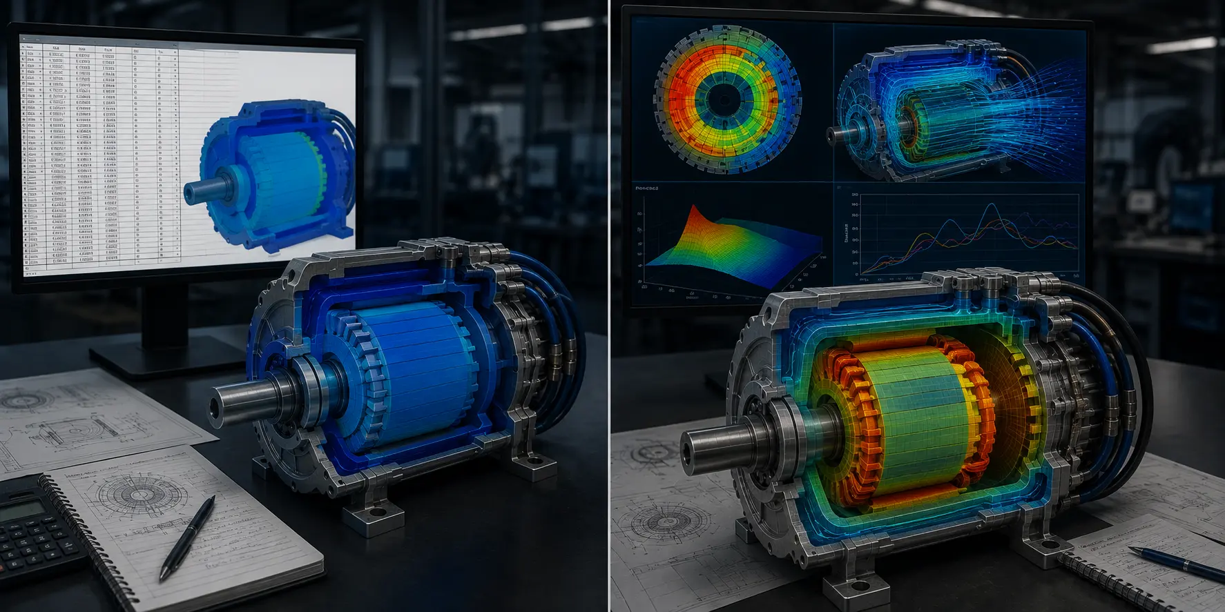
Ask most thermal engineers how they get loss data from the EMag team, and the answer is usually: a spreadsheet. Copper loss, iron loss, magnet eddy current loss — calculated at a handful of operating points, exported as static numbers, and pasted into a thermal model as fixed boundary conditions.
That handoff loses information in three places. First, it's usually calculated at only a few load points, not the full duty cycle. Second, it's static — it doesn't account for how losses shift as temperature rises (winding resistance increases with heat, which increases copper loss, which raises temperature further). Third, it's manual, which means every design iteration means someone re-running numbers and re-copying them, with real risk of a stale value slipping through unnoticed.
What "Coupled" Actually Means
A properly coupled workflow passes the electromagnetic loss map directly into the thermal solver as a function of operating point and, ideally, temperature — so the thermal model sees the same transient loss behavior the motor will actually experience, not a handful of static snapshots.
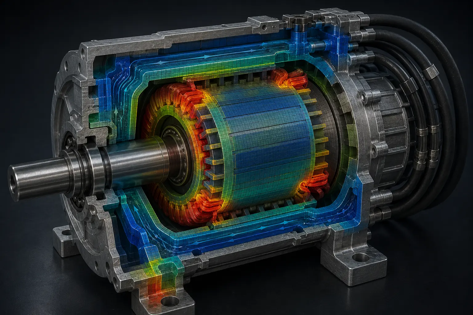
When magnet temperature is part of that loop, you also get a read on demagnetization risk: rare-earth magnets lose coercivity as they heat up, and past a certain point that demagnetization becomes irreversible. Class F and Class H insulation limits define your winding ceiling; the magnet's temperature-dependent coercivity curve defines the other one. Both need real transient data, not a single worst-case number, to design against with confidence.
Where This Bites Hardest
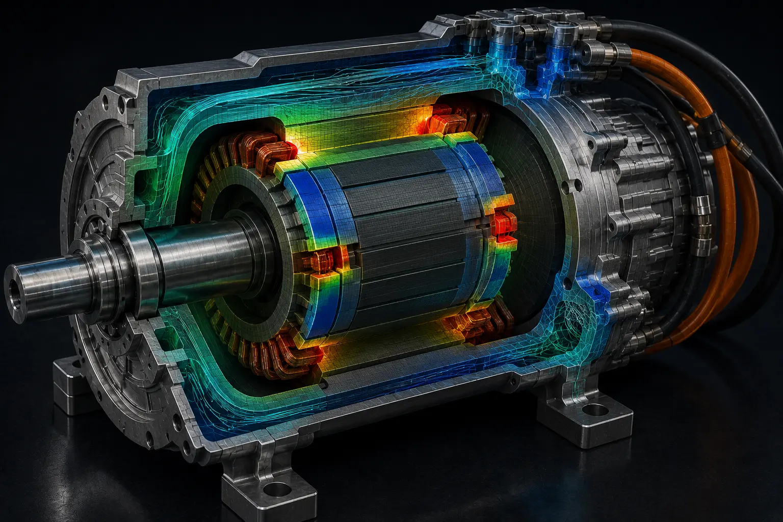
At high operating frequencies (10–20+ kHz SiC switching), standard low-frequency sinusoidal estimates fail. SiC inverter PWM harmonics induce non-negligible high-frequency iron losses and rotor magnet eddy current losses.
Setting It Up Properly
A coupled EMag-thermal workflow, done right, looks like:
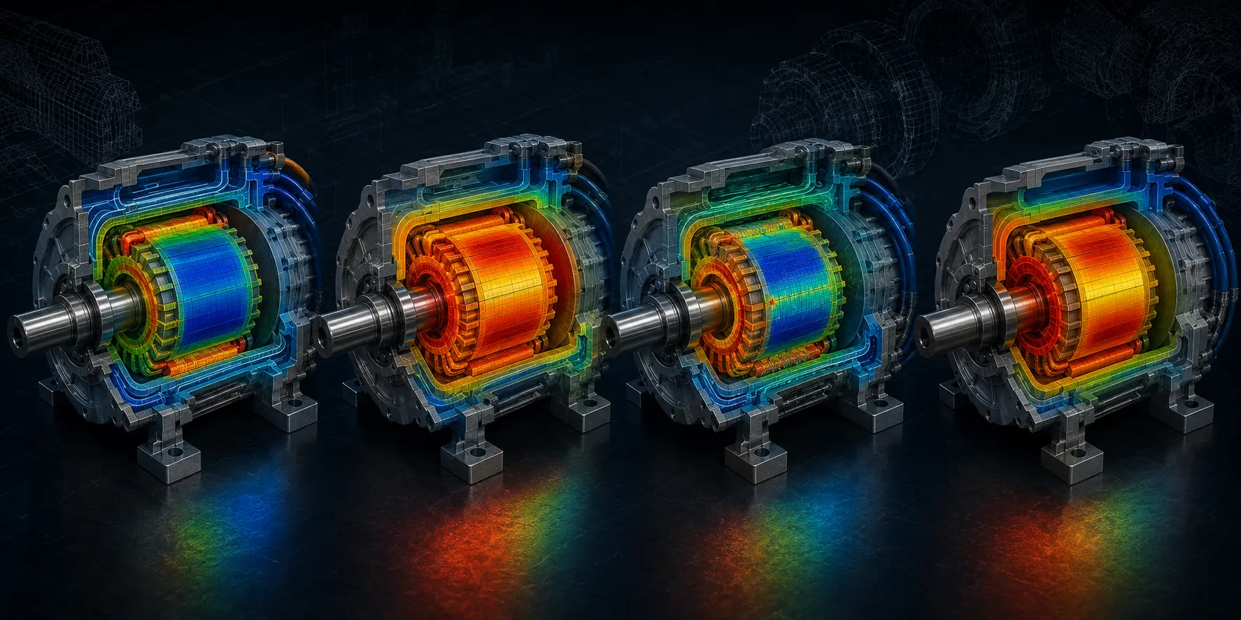
- Generate the loss map (copper, iron, magnet eddy current) across the full torque-speed operating envelope, not just rated point
- Pass it into the thermal solver as a function of operating point and winding/magnet temperature
- Run the coolant-side model (water jacket, oil spray) against real transient duty cycles, not steady-state assumptions
- Check peak magnet temperature against the demagnetization curve at end-of-life conditions, not fresh-magnet properties
- Iterate the loop — because a hotter magnet changes electromagnetic performance, which changes the loss map you started with
Most teams do step 1 well and stop there. The teams that avoid late-stage demagnetization surprises are the ones that close the loop back to step 5.
Is Your 800V Motor Thermal Workflow Coupled — or Still Spreadsheet-Based?
Kaizenat's CAE engineers help thermal and EMag teams implement coupled electromagnetic-thermal simulation — closing the loss-map loop before demagnetization risk shows up at prototype stage.